
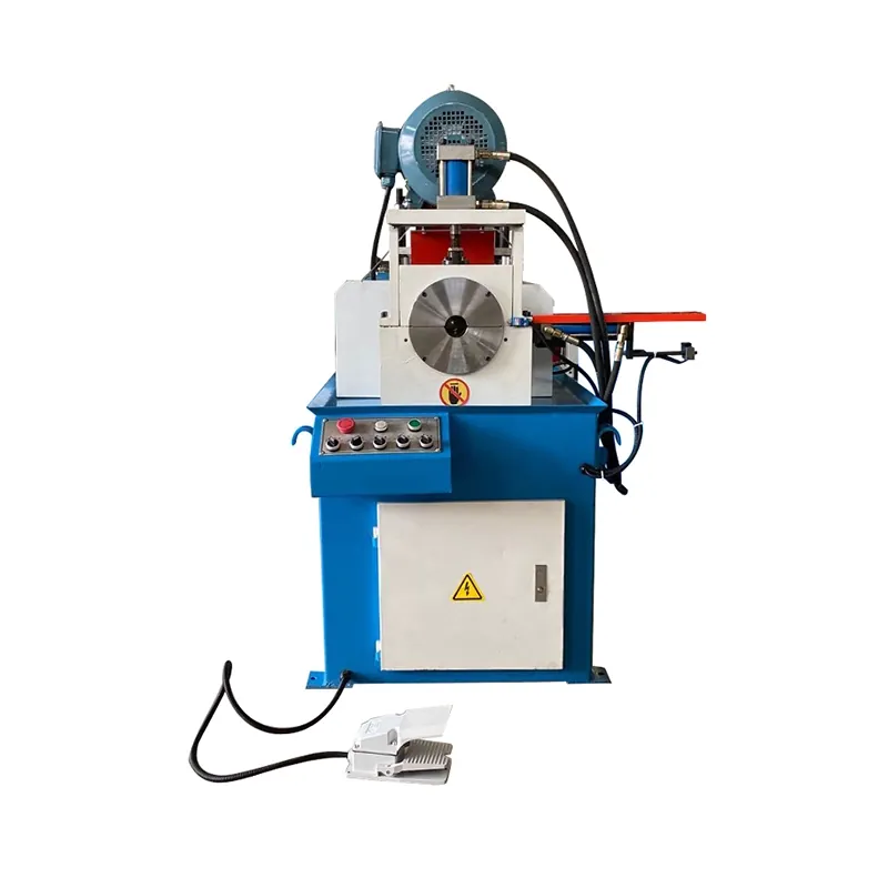
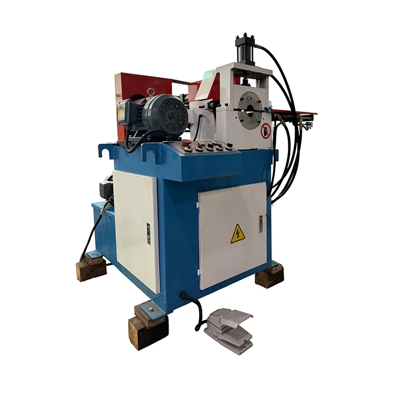
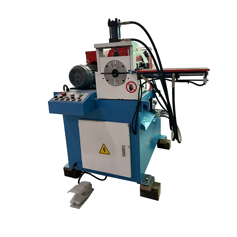
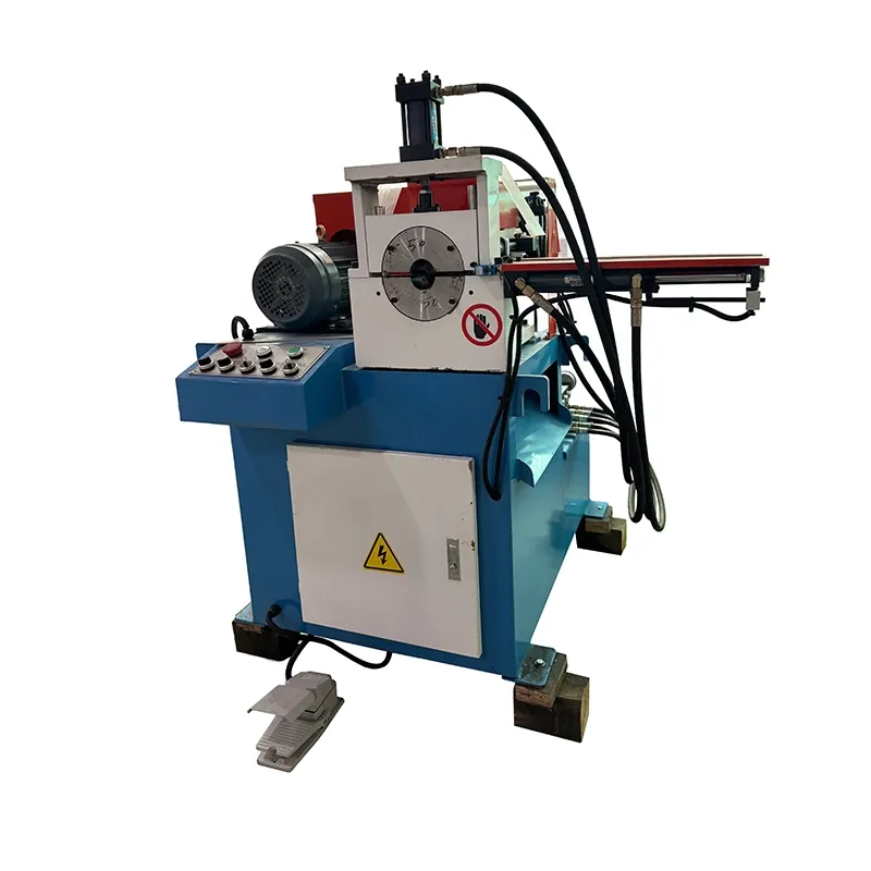
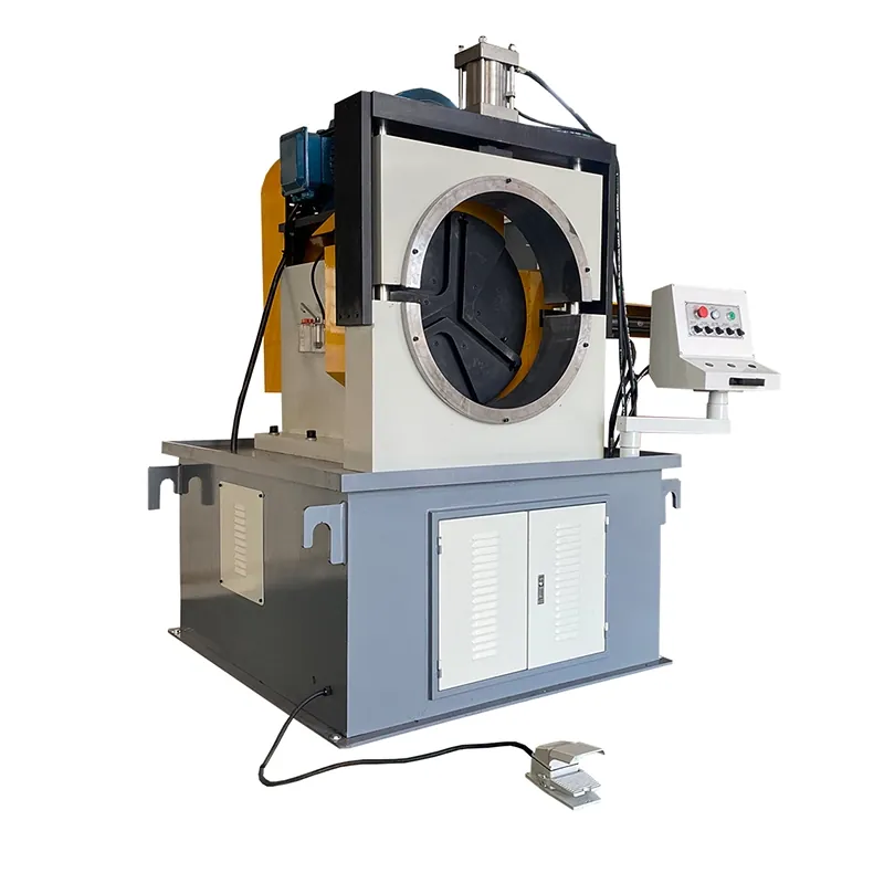
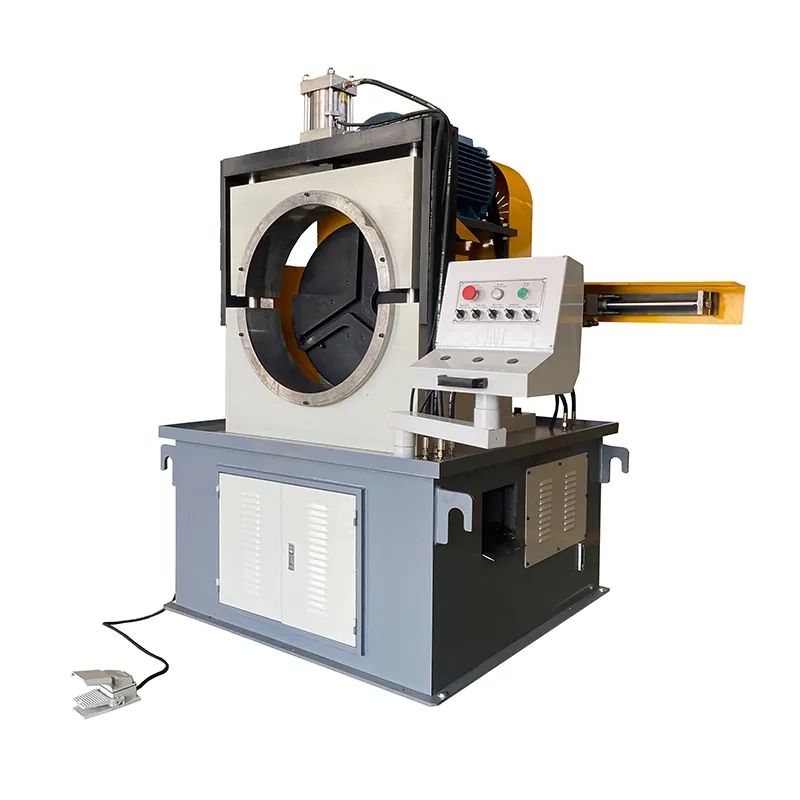
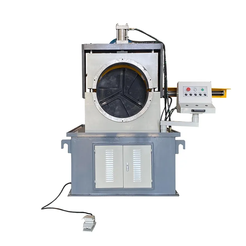
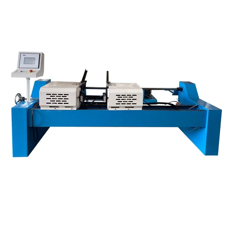
Single-Head Automatic Pipe Chamfering Machine
Automatic single-end chamfering and facing station for pipe and solid bar. Pedal-start cycle performs external chamfer, internal chamfer and end facing in one pass — 3-5 second cycle, ±0.1 mm length tolerance. Pneumatic (DC) for thin-wall high speed; hydraulic (DY) for heavy-wall thick pipe and bar.
Pick your size — 9 models in the series.
| DC-60 Pneumatic · Ø 3 – 60 mm | DC-80 Pneumatic · Ø 18 – 80 mm | DC-120 Pneumatic · Ø 20 – 120 mm | DC-180 Pneumatic · Ø 30 – 160 mm | DY-80B Hydraulic · Ø 15 – 80 mm | DY-120B Hydraulic · Ø 15 – 120 mm | DY-230 Hydraulic · Ø 60 – 230 mm | DY-300B Hydraulic · Ø 80 – 300 mm | DY-450B Hydraulic · Ø 100 – 425 mm | |
|---|---|---|---|---|---|---|---|---|---|
| Pipe OD range | 3 – 60 mm | 18 – 80 mm | 20 – 120 mm | 30 – 160 mm | 15 – 80 mm | 15 – 120 mm | 60 – 230 mm | 80 – 300 mm | 100 – 425 mm |
| Wall thickness | thin wall | thin wall | thin wall | thin wall | 0.6 – 8 mm | 1 – 12 mm | 1 – 15 mm | 0.6 – 15 mm | 2 – 20 mm |
| Motor power | 0.75 kW | 1.5 kW | 4.0 kW | 4.0 kW | 2.2 kW | 4.0 kW | 5.5 kW | 7.5 kW | 11 kW |
| Solid bar capacity | Ø 0.5 – 3 mm | Ø 1 – 4 mm | Ø 1 – 4 mm | Ø 1 – 4 mm | Ø 50 mm | Ø 50 mm | Ø 60 mm | Ø 30 mm | Ø 20 mm |
| Cycle time | 3 – 5 s/pc | 3 – 5 s/pc | 3 – 5 s/pc | 3 – 5 s/pc | 5 – 8 s/pc | 5 – 8 s/pc | 5 – 8 s/pc | 5 – 8 s/pc | 5 – 8 s/pc |
| Length tolerance | ±0.1 mm | ±0.1 mm | ±0.1 mm | ±0.1 mm | ±0.1 mm | ±0.1 mm | ±0.1 mm | ±0.1 mm | ±0.1 mm |
| Quote this model |
How automatic pipe chamfering replaces lathe work
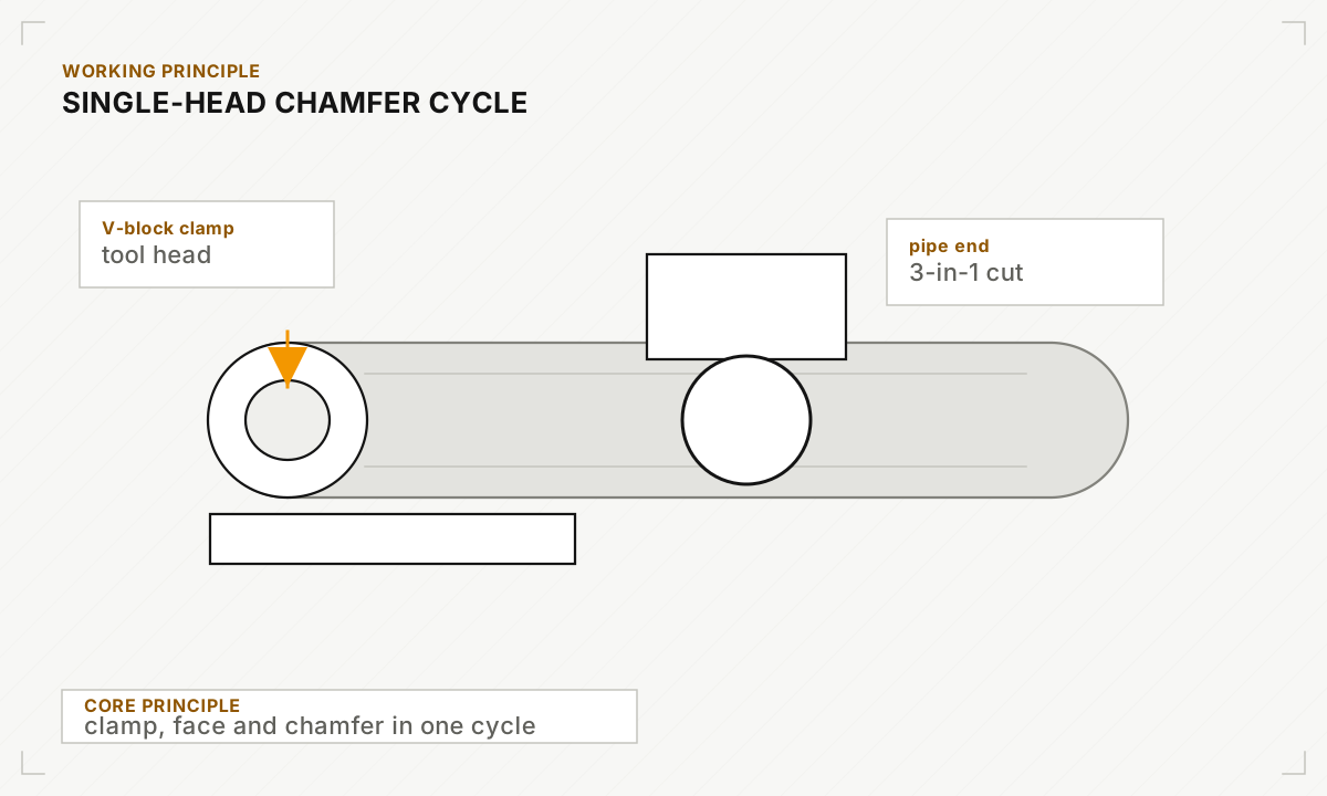
A manual lathe operator typically takes 60 – 90 s per pipe end to chuck, set tool depth, face, chamfer, and unchuck — and the result varies with operator skill. The single-head chamfering machine inverts the workflow: the operator only places the pipe in the V-block and steps on a foot pedal. The machine pneumatically (DC) or hydraulically (DY) clamps the pipe, axially feeds a multi-tool head that simultaneously cuts the external chamfer, internal chamfer and end face in 3 – 5 seconds, then retracts and releases. Operator productivity rises 10×+ versus lathe work, and length tolerance stays at ±0.1 mm regardless of operator fatigue — which is the actual requirement for downstream robotic welding and assembly.
Built for the job site.
Where this series earns its keep.
Automotive tubing & exhaust prep
Shock-absorber tubes, exhaust pipe, bushing stock — high-volume chamfering for downstream MIG/MAG welding. Length tolerance on the chamfering machine sets the achievable weld-cell throughput.
Furniture, lighting & metal goods
Tube ends for table legs, chair frames, lighting structures and display fixtures. DC pneumatic models dominate this segment for the cycle speed and low operating cost.
Hydraulic cylinder & seamless pipe
Heavy-walled hydraulic pipe and pressure-tube end-prep for cylinder fabrication. DY hydraulic for the wall thicknesses (8 – 20 mm) typical of cylinder stock.
Common questions about the DC / DY Single-Head.
Can't find your answer?
Single-head or double-head — which should I order?
Why pneumatic vs hydraulic?
Can it chamfer square tubing or just round?
What chamfer geometries are possible?
Other automatic chamfering machines.
Get a quote within 24 hours.
Send us your spec sheet, pipe schedule, or drawing — our engineers reply with pricing, lead time, and recommended models.
- 01Send specs & drawings
- 02Receive quote within 24h
- 03Confirm & manufacture